Hybrid Inverter MPPT Sizing: How to Match PV Strings to Voltage, Current and Power Limits
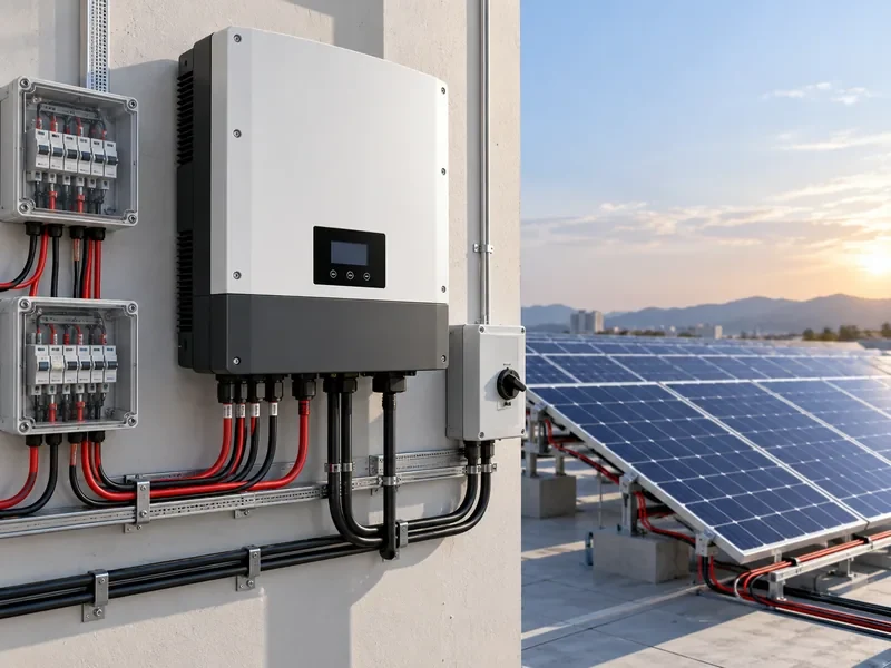
A hybrid inverter can have the correct AC power rating and still be unsuitable for a solar PV array. For installers, distributors and solar-storage project buyers, one of the most important compatibility checks is the relationship between the photovoltaic strings and the inverter’s maximum power point tracking (MPPT) inputs.
A 5kW hybrid inverter, for example, may support the required household load but have insufficient PV input-current capacity for the selected high-current modules. Another inverter may accept the operating string voltage under standard test conditions but exceed its maximum DC voltage during cold weather.
These problems are not always visible in a product catalogue. They become apparent when the PV module datasheet, inverter specifications, local environmental conditions and proposed string arrangement are reviewed together.
Hybrid inverter MPPT sizing means checking the PV array’s operating voltage, maximum open-circuit voltage, current and string configuration against the inverter’s actual DC input specifications. A suitable design must account for cold-weather Voc, hot-weather Vmp, input-current and short-circuit-current limits, MPPT quantity and the manufacturer’s permitted PV power.
This guide explains the calculations and technical checks that installers and procurement teams should complete before selecting or sourcing hybrid inverters.
1. What Is MPPT Sizing in a Hybrid Inverter?
Maximum Power Point Tracking (MPPT) is a control function that adjusts the operating point of a photovoltaic array to obtain power close to its available maximum under changing sunlight and temperature conditions.
Solar modules do not operate at a fixed voltage. Their voltage and current change with cell temperature, irradiance and the electrical load imposed on the array.
A hybrid inverter’s MPPT controller continuously adjusts the DC operating point within its supported tracking range. However, it cannot overcome the inverter’s fundamental voltage and current limits.
When reviewing a hybrid inverter datasheet, pay attention to the following specifications:
- Maximum PV input voltage: The maximum permitted DC voltage at the inverter input.
- MPPT operating voltage range: The voltage range within which the tracker can operate.
- PV startup voltage: The voltage required for the inverter to initiate PV operation under specified conditions.
- Full-load MPPT voltage range: The voltage range over which rated or specified output can be maintained, where the manufacturer provides this information.
- Maximum input current: The current the inverter or tracker can process under the stated operating conditions.
- Maximum short-circuit current: The PV source short-circuit-current limit specified for the relevant input or tracker.
- Number of MPPTs: The number of independently controlled tracking channels.
- PV string inputs: The physical string connections available and their internal electrical arrangement.
These specifications must be checked individually. A wide MPPT voltage range does not automatically mean that an inverter can accept any solar module or string configuration.
SMA’s PV input requirements explicitly require cold-day Voc and input limits to be respected. The SMA engineering overview explains temperature-dependent PV behavior and MPP tracking. These explain the checks used below; they do not approve a particular ORIDY configuration.
2. Understanding PV Module Voltage and Current Specifications
Before evaluating the inverter, installers need the electrical characteristics of the exact PV module selected for the project.
| Parameter | Meaning | Why It Matters |
|---|---|---|
| Voc | Open-circuit voltage | Used to evaluate maximum string voltage, particularly under cold conditions. |
| Vmp | Voltage at maximum power | Used to evaluate whether the string operates within the MPPT tracking range. |
| Isc | Short-circuit current | Used for input-current limits and relevant protection and conductor design checks. |
| Imp | Current at maximum power | Used to assess expected operating current and potential input-current limiting. |
| Pmax | Maximum module power at STC | Used to calculate the PV array’s nameplate capacity. |
| Temperature coefficients | Changes in voltage or other characteristics with temperature | Used to evaluate voltage under expected site conditions. |
Standard Test Conditions (STC) generally refer to a module cell temperature of 25°C, irradiance of 1,000 W/m² and an AM1.5 reference spectrum.
Real installations operate under different conditions. Module temperature may rise considerably above 25°C on a sunny roof, while low ambient temperatures can increase open-circuit voltage.
For that reason, using only the voltage and power values printed on a module’s sales brochure is not sufficient for final string design.
3. How to Calculate Maximum PV String Voltage in Cold Weather
Cold-weather open-circuit voltage is one of the most important checks in hybrid inverter MPPT sizing.
When module temperature decreases, open-circuit voltage generally increases. A PV string that appears acceptable at STC may exceed the inverter’s maximum DC input voltage under cold conditions.
Cold-Weather Voc Calculation
For a simplified calculation using a linear voltage temperature coefficient:
Voc(cold) = Voc(STC) × [1 + βVoc × (Tcold − 25°C)]
Here, βVoc is the signed temperature coefficient expressed per °C. A typical negative coefficient produces a positive voltage increase when the temperature falls below 25°C.
For a series string:
String Voc(cold) = Number of modules in series × Voc(cold)
Worked Example: Nine Modules in Series
Consider a hypothetical PV module with the following values:
- Module Voc at STC: 49.5V
- Voc temperature coefficient: −0.28%/°C
- Assumed minimum module temperature: −10°C
- Modules connected in series: 9
- Proposed inverter maximum DC input voltage: 500V
First calculate the temperature difference:
−10°C − 25°C = −35°C
The corresponding voltage increase is:
(−0.0028) × (−35) = 0.098 = 9.8%
Cold-weather module Voc:
49.5V × 1.098 = 54.351V
Cold-weather string Voc:
54.351V × 9 = 489.159V
The calculated string voltage is approximately 489.2V.
Under these simplified assumptions, the result is below the proposed inverter’s 500V maximum DC input voltage. However, the remaining difference is only about 10.8V, or approximately 2.2% of the inverter limit.
This calculation does not establish that the design is acceptable. The installer must confirm the correct site design temperature, the module manufacturer’s temperature coefficient, applicable voltage correction methods, measurement tolerances, relevant local electrical rules and any required design margins.
If the inverter’s maximum voltage is exceeded under the applicable design conditions, the string configuration must be changed or a different inverter selected.
The exact calculation and design method should be verified against the applicable local requirements and the PV module manufacturer’s documentation. IEC 62548-1, Photovoltaic arrays — Design requirements, is a relevant international reference for PV array design.
4. How to Check the MPPT Operating Voltage Range in Hot Conditions
Cold-weather Voc establishes an important upper-voltage check. Hot-weather operating voltage helps determine whether the PV string can remain within the inverter’s usable MPPT tracking range.
PV module operating voltage generally decreases as cell temperature increases.
This can be particularly important for residential systems with short strings or inverters with relatively high minimum MPPT voltages.
Example: Hot-Weather Vmp Calculation
Assume a hypothetical module has:
- Vmp at STC: 41.5V
- Vmp temperature coefficient: −0.30%/°C
- Assumed operating cell temperature: 65°C
- Number of series modules: 8
- Inverter MPPT operating range: 120–430V
Using a simplified linear approximation:
Vmp(hot) = Vmp(STC) × [1 + βVmp × (Thot − 25°C)]
Temperature difference:
65°C − 25°C = 40°C
Voltage adjustment:
1 + (−0.0030 × 40) = 0.88
Hot-weather module Vmp:
41.5V × 0.88 = 36.52V
Hot-weather string Vmp:
36.52V × 8 = 292.16V
The calculated operating string voltage is approximately 292.2V, which lies within the example inverter’s 120–430V MPPT range.
For comparison, the same string has an STC Vmp of:
41.5V × 8 = 332V
The difference illustrates why operating temperature matters even when the number of solar modules remains unchanged.
However, this example is not a final design approval. Actual module temperature, the correct manufacturer-provided coefficient, the inverter’s full-load MPPT range and the interaction between voltage, current and available power must also be considered.
Startup Voltage Is Not the Same as Minimum MPPT Voltage
Some inverter datasheets specify different values for startup voltage and minimum MPPT operating voltage.
For example, a hypothetical inverter may specify:
- PV startup voltage: 100V
- MPPT operating range: 120–430V
A PV string producing 110V may satisfy a startup threshold under certain conditions but still be below the normal MPPT tracking range.
Buyers should not treat startup voltage as the minimum recommended string operating voltage.
Check Both Ends of the Tracking Window
Hot-weather Vmp is the lower-bound check; also compare cold-weather Vmp with the upper tracking limit. Using the earlier illustrative 41.5V Vmp, a hypothetical −0.35%/°C Vmp coefficient and −10°C module temperature gives 41.5 × [1 + 0.0035 × 35] = 46.58375V per module. Ten modules give approximately 465.84V: outside a hypothetical 430V upper MPPT limit even if cold Voc remains below a separate maximum DC limit. These assumed values are not product specifications. Use the actual module coefficient, design temperatures and inverter full-power tracking window.
5. Matching PV String Current to Hybrid Inverter MPPT Inputs
Voltage is only part of the compatibility check. Modern high-power PV modules may have relatively high operating and short-circuit currents, which can create problems when paired with older inverter designs.
For modules connected in series, string voltage increases while string current remains approximately equal to the current of an individual module under matched operating conditions.
For identical strings connected in parallel, current increases while the nominal string voltage remains approximately the same.
Example: Two Parallel PV Strings
Assume each identical PV string has:
- Operating current (Imp): 13A
- Short-circuit current (Isc): 13.8A
For two parallel strings:
Total Imp = 13A × 2 = 26A
Total Isc = 13.8A × 2 = 27.6A
The proposed inverter must be checked against both current-related specifications.
If an MPPT has a maximum usable operating input current of 20A, a 26A operating-current capability from the connected array may result in current limiting under suitable irradiance conditions.
That does not, by itself, establish whether the configuration is permitted. The separate short-circuit-current limit, the manufacturer’s oversizing guidance and the relevant input architecture must also be checked.
Never assume that exceeding an operating-current rating is acceptable simply because the inverter may limit harvested power. The manufacturer must explicitly permit the proposed configuration, and the PV array’s design short-circuit current must satisfy the applicable equipment and electrical-code limits.
Imp and Isc Must Be Evaluated Separately
Imp represents the current at the module’s maximum power point, while Isc represents the short-circuit current under the specified measurement conditions.
These values serve different purposes.
For procurement, request both the maximum operating input current and maximum permitted PV short-circuit current for each relevant input or MPPT.
Also determine whether current limits apply to individual physical inputs, a complete tracker, or internally paralleled input groups.
For parallel strings, the designer must check possible reverse current into a faulted string against the module backfeed limit, maximum series-fuse rating, cable and connector ratings, and the manufacturer’s required protection. Fronius’s string-fuse guidance illustrates these separate checks; its product-specific fuse choices must not be applied universally. Use the exact equipment manual and applicable installation rules.
Do not use STC Isc alone as the final design current. Account for the site’s design irradiance, applicable temperature/current correction, and any bifacial rear-side contribution using module data and the governing design method. Confirm the adjusted current against every relevant input, tracker, connector and protection limit; no universal multiplier is assumed here.
6. Single MPPT vs Dual MPPT: Which Configuration Is Better?
The number of MPPT trackers affects how independently the inverter can control different photovoltaic arrays.
Consider a residential roof with two solar panel groups:
- One group faces east.
- Another group faces west.
The two groups receive different irradiance throughout the day, and their optimal operating points may differ.
With two independent MPPT channels, the installer may connect the east-facing string to MPPT 1 and the west-facing string to MPPT 2, provided each string satisfies the respective input requirements.
This allows the inverter to track the two arrays independently.
By contrast, combining arrays with significantly different electrical characteristics or operating conditions on one MPPT can reduce energy harvest or create unsuitable operating conditions.
When Multiple MPPTs Are Particularly Useful
- East-west roof orientations
- Different roof tilts
- Arrays with substantially different shading patterns
- Separate roof sections with different electrical configurations
- Projects requiring independent string groups within the manufacturer’s supported design
However, the number of physical PV string connectors is not necessarily the number of independent MPPT trackers.
An inverter advertised as having two MPPTs and four PV string inputs may connect two physical inputs to each tracker internally. The exact arrangement must be confirmed from the manufacturer’s wiring diagram and installation manual.
For distributors, this distinction is important because two inverters with the same AC output power and MPPT count may have different current capacities and string-connection flexibility.
7. Can PV Array Power Be Higher Than Hybrid Inverter AC Power?
Yes. Some hybrid inverters permit a PV array with a DC nameplate capacity higher than the inverter’s rated AC output power.
This practice is commonly described as DC/AC oversizing.
For example, a 5kW inverter might be paired with more than 5kWp of PV modules if its manufacturer explicitly permits the proposed array configuration.
Oversizing may improve energy harvest during periods of lower irradiance, but it can also lead to power clipping or curtailment when the available PV power exceeds what the inverter and connected system can use.
Hybrid inverters introduce additional considerations because PV power may be directed to household loads, battery charging and permitted grid export, depending on the system architecture and operating mode.
Therefore, procurement teams should verify:
- Maximum or recommended PV array power
- Maximum DC input voltage
- MPPT operating and short-circuit-current limits
- Inverter AC output rating
- Battery charging power and current limits
- Permitted simultaneous PV-to-load and PV-to-battery operation
- Grid export restrictions in the destination market
- Manufacturer guidance on DC/AC oversizing
A high advertised maximum PV power rating does not override the inverter’s voltage, current or string-configuration limits.
For buyers comparing multiple products, our hybrid inverter wholesale guide discusses additional commercial considerations involved in sourcing hybrid inverter systems.
8. Worked Example: Selecting a Hybrid Inverter for a Residential Solar-Storage System
Consider a hypothetical residential solar-storage project with the following initial requirements:
| Project Parameter | Example Requirement |
|---|---|
| Inverter AC rating | 5kW |
| Grid connection | Single-phase |
| PV module power | 450W |
| Number of PV modules | 10 |
| Module Voc at STC | 49.5V |
| Module Vmp at STC | 41.5V |
| Module Imp | Approximately 10.84A (450W ÷ 41.5V) |
| Module Isc | 13.8A |
| Battery system | To be confirmed |
These are illustrative project assumptions, not specifications for a particular ORIDY-supplied inverter or PV module.
Step 1: Calculate Total PV Nameplate Power
10 × 450W = 4,500W = 4.5kWp
The array’s nameplate power is 4.5kWp.
Step 2: Calculate String Voltage at STC
If all 10 modules are connected in one series string:
String Voc = 10 × 49.5V = 495V
String Vmp = 10 × 41.5V = 415V
These values must be compared with the proposed inverter’s maximum DC voltage and MPPT tracking range.
Step 3: Apply Cold-Weather Voltage Correction
Assuming the same hypothetical −0.28%/°C Voc coefficient and −10°C minimum module temperature used earlier:
Cold module Voc = 54.351V
Cold string Voc = 10 × 54.351V = 543.51V
A proposed inverter with a 500V maximum PV input would not satisfy this simplified cold-voltage check.
An alternative inverter with a higher permitted DC voltage might be considered, or the array could be divided into different strings if the MPPT architecture, current limits and other design requirements allow it.
Step 4: Check Current Compatibility
With one series string, the STC operating current is approximately 10.84A and the STC short-circuit current is approximately 13.8A.
The inverter’s maximum operating input current and permitted PV short-circuit current must be checked separately, including any applicable current adjustments required by the design standard or local code.
Step 5: Confirm Battery and Grid Compatibility
Even if the PV array is electrically compatible, the inverter may still be unsuitable for the proposed energy-storage system.
Additional checks include:
- Supported battery voltage range
- Maximum battery charge and discharge current
- Supported BMS communication protocols
- Actual battery-inverter compatibility documentation
- Grid phase, voltage and frequency
- Backup output and operating-mode requirements
- Applicable grid connection and safety documentation for the destination market
See our battery and inverter compatibility guide for related system-matching considerations.
Procurement conclusion: A 5kW AC power rating and 4.5kWp PV array rating are not enough to approve an inverter. The complete PV input, battery and grid specifications must be evaluated against the actual installation requirements.
9. Hybrid Inverter Procurement Checklist for Installers and Distributors
Before requesting a quotation, buyers should prepare the information required for a meaningful technical comparison.
| Information Required | What to Provide or Verify |
|---|---|
| Destination market | Country and applicable grid requirements |
| Inverter rating | Required AC power, phase, voltage and frequency |
| PV module | Exact model and electrical datasheet |
| PV configuration | Modules per string, number of strings and proposed MPPT allocation |
| Site conditions | Minimum design temperature and expected maximum operating temperature |
| MPPT specifications | Voltage range, number of trackers and input architecture |
| Current limits | Maximum operating input current and permitted short-circuit current |
| Battery | Model, voltage, capacity, current limits and BMS communication requirements |
| Operating mode | Grid-connected, backup, self-consumption or other required functions |
| Documentation | Datasheets, installation manuals and applicable model-level compliance evidence |
| Commercial requirements | Estimated quantity, delivery destination, warranty expectations and target schedule |
Where safety and compliance documentation is required, buyers should request evidence for the exact inverter model rather than assuming that every product within a supplier’s catalogue holds the same approvals.
IEC 62109-1, Safety of power converters for use in photovoltaic power systems, is a relevant safety reference. Applicable requirements and evidence must still be determined for the specific product and destination market.
Need Help Sourcing a Hybrid Inverter from China?
ORIDY ENERGY supports overseas solar installers, distributors and renewable-energy project buyers with China-side hybrid inverter sourcing and specification coordination.
Share your destination market, PV module datasheet, proposed string layout, required inverter power, battery specifications and expected order quantity. We can help you compare relevant supply options and coordinate the technical questions needed before requesting a formal quotation.
Review our hybrid solar inverter product category for available product directions. Final design and local compliance must be confirmed for the exact equipment by the responsible qualified professionals.
Share your PV module datasheet and proposed string layout through our inverter sourcing inquiry form so we can coordinate the specifications that need confirmation.