
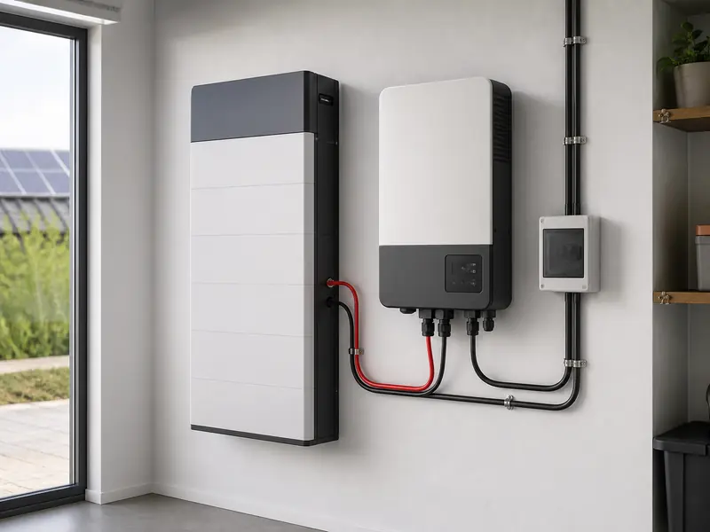
How Battery Discharge Current Limits Inverter Power
A battery can store enough energy for several hours and still be unable to run an inverter at full power. This guide explains how battery discharge current limits inverter power: the available amperes, operating voltage and battery management system (BMS) limit determine how much DC power can reach the inverter.
For installers and distributors, this distinction prevents a common specification error. Battery capacity in kilowatt-hours (kWh) determines how much energy is stored; inverter power in kilowatts (kW) determines how quickly energy must be delivered. To check whether a battery can support an inverter, compare voltage, continuous discharge current, short-duration current, inverter demand and the limits communicated by the BMS.
How Battery Discharge Current Limits Inverter Power
The approximate DC power available from a battery is voltage multiplied by current:
Battery DC power (W) = battery voltage (V) × discharge current (A)
A nominal 51.2V battery limited to 100A can provide approximately 5.12kW DC at nominal voltage. The inverter cannot convert all of that into 5.12kW AC because conversion has losses and the battery voltage changes during operation. A conservative initial check is:
Estimated AC power = operating battery voltage × permitted discharge current × inverter efficiency
If an example system operates at 50V, permits 100A and is assumed to convert at 94% efficiency, the estimate is 50 × 100 × 0.94 = 4.7kW AC. This is an engineering estimate, not a product guarantee. Use the exact battery and inverter documentation for final design.
Why kWh Does Not Tell You the Available kW
Energy capacity and power capability answer different questions. A 10kWh battery describes stored energy. It does not, by itself, say whether the battery can deliver 3kW, 5kW or 10kW continuously.
| Parameter | What it describes | What to verify |
|---|---|---|
| kWh | Stored energy and potential runtime | Nominal capacity, usable depth of discharge and system losses |
| kW | Rate of power delivery | Inverter output and load demand |
| A | Battery current | Continuous, peak and BMS-controlled discharge limits |
| V | Battery operating voltage | Inverter input range and voltage under load |
This is why two batteries with the same capacity can support different inverter power. Their cell configuration, BMS, current rating, thermal design, connectors and parallel-operation rules may differ. Buyers comparing battery systems should therefore evaluate both energy and power.
For a wider architecture comparison, see ORIDY ENERGY’s guide to low-voltage vs high-voltage battery systems. At the same power, a lower-voltage system must carry more current, which affects battery-bank sizing, conductors and protection.
Continuous Current and Peak Current Are Not Interchangeable
The continuous discharge-current rating is the current a battery is designed to supply for sustained operation under specified conditions. A peak or pulse rating applies only for a stated short duration and may be conditional on state of charge, temperature or prior load.
Do not size a system’s normal output from the peak figure. Motor starts, pumps, compressors and other loads can create short surges, but the battery bank, inverter and conductors must all handle the relevant duration. If a surge exceeds the BMS threshold, the BMS may reduce discharge permission or disconnect the battery.
Manufacturer documentation illustrates why the distinction matters. Victron’s current smallBMS NG guidance lists separate continuous and ten-second pulse discharge limits and instructs designers to keep combined loads within battery limits. Those values apply to the named products, not to lithium batteries universally.
How Much Battery Current Does an Inverter Need?
For an initial estimate, divide required AC power by battery voltage and assumed inverter efficiency:
Estimated DC current (A) = required AC power (W) ÷ (operating battery voltage × inverter efficiency)
| Example AC output | Assumptions | Estimated battery current |
|---|---|---|
| 3kW | 50V under load, 94% efficiency | About 64A |
| 5kW | 50V under load, 94% efficiency | About 106A |
| 8kW | 50V under load, 94% efficiency | About 170A |
These examples show why a single 100A battery may not support 5kW AC continuously once operating voltage and conversion losses are considered. They also show why calculating from 51.2V nominal voltage alone can overstate the margin.
The final calculation should use the inverter manufacturer’s DC-current data or efficiency information, the battery’s permitted current, the expected voltage under load and any design margin required by the manufacturers or local engineering practice.
What the BMS Changes During Operation
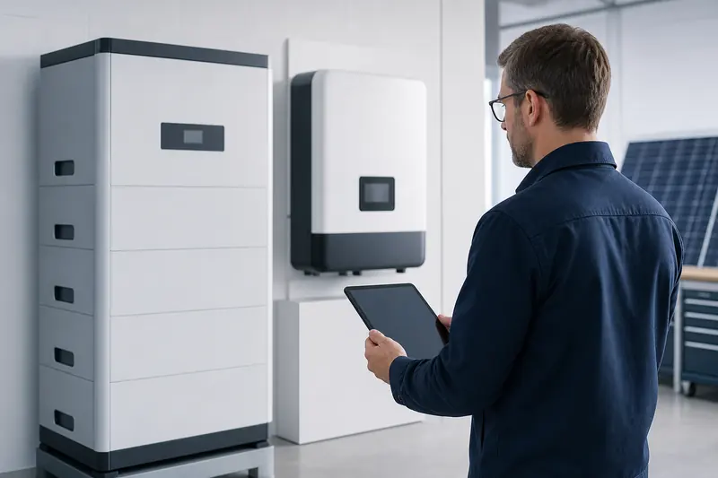
In a closed-loop system, the battery may communicate a dynamic Discharge Current Limit (DCL) to the inverter. That value can be lower than the headline datasheet maximum. The permitted current may change with state of charge, cell voltage, temperature, faults or the number of battery modules online.
Victron’s DVCC documentation identifies DCL as one of the battery parameters passed to connected inverter/chargers. Its battery integration guidance also shows that battery banks must be sized for both continuous and surge demand. This behaviour depends on the exact inverter, battery, firmware and operating mode.
If communication is absent or incompatible, the system may operate using manually configured voltage and current settings, or it may refuse operation. A matching CAN or RS485 connector does not prove protocol compatibility. Check the complete battery and inverter compatibility path, including protocol, firmware, approved device combinations and fail-safe behaviour.
Inverter selection matters too. A broader hybrid inverter procurement guide can help buyers compare battery-current input, backup output, MPPT configuration, phase architecture and documentation as part of the same RFQ.
Can Parallel Batteries Increase Available Power?
Parallel battery modules can increase total current capability when the product is designed and approved for parallel operation. In a simplified case, two identical modules each permitted to deliver 100A could provide a 200A bank limit. The actual system limit may be lower because of the master BMS, busbars, cables, protective devices, communication architecture or inverter input limit.
Before using module count as a power solution, verify:
- the maximum supported number of parallel modules;
- whether current limits scale with every online module;
- required firmware and communication wiring;
- busbar, cable, fuse and disconnect ratings;
- module matching and commissioning procedure;
- the inverter’s maximum battery input current.
Do not assume that adding energy capacity always increases usable power in direct proportion. The manufacturer’s system-level limit controls.
Common Symptoms of an Undersized Battery Bank
| Symptom | Possible current-related cause | What to check |
|---|---|---|
| Inverter will not reach rated output | BMS DCL or configured current limit is lower than demand | Live DCL, inverter settings and battery-module count |
| System trips when a large load starts | Surge demand exceeds a battery or BMS threshold | Load surge profile and every component’s time-based rating |
| Output falls at low state of charge | Battery voltage or dynamic DCL decreases | Voltage under load, cell limits and communicated DCL |
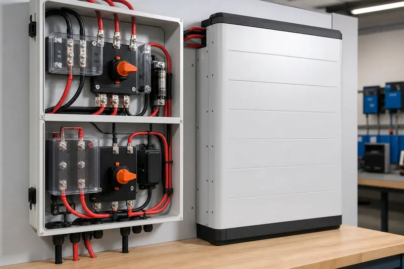
| Cables or terminals run hot | Excess current, resistance or poor termination | Stop operation and have a qualified professional inspect the DC path |
These symptoms are not proof of one fault. Logs, BMS data, inverter alarms and measurements taken by qualified personnel are needed. Safety-critical DC work should follow the equipment instructions and applicable installation rules.
What to Confirm Before Ordering
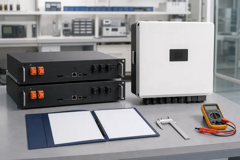
A battery-and-inverter RFQ should make the required power explicit. “10kWh battery for a 5kW inverter” is not enough information.
- Inverter: exact model, rated AC power, surge requirement, battery-voltage range and maximum DC current.
- Battery: exact model, nominal and operating voltage, continuous and peak discharge current, and peak duration.
- Communication: CAN or RS485 protocol, supported firmware, compatibility listing and behaviour if communication fails.
- Bank design: required module count, parallel limit, current scaling and master/slave architecture.
- Application: continuous loads, starting loads, backup duration, expected temperature and future expansion.
- DC hardware: approved cables, connectors, busbars, fuses, isolators and installation distances.
- Commercial scope: quantity, destination market, required model-specific documentation, OEM or ODM needs, Incoterm and delivery destination.
Request the actual datasheets, manuals and compatibility evidence before a sample or bulk order. Certification requirements and available documentation depend on the selected model and target market; one supplier’s evidence must not be generalized to a different product.
The Practical Selection Rule
Start with the required continuous AC power and surge profile. Convert that demand into DC current using a realistic operating voltage and efficiency, then compare the result with the battery bank’s continuous limit, dynamic BMS limit and short-duration capability. Finally, verify the inverter’s own DC input limit and the rating of the complete DC path.
For a compatibility and sourcing review, send ORIDY ENERGY the inverter model, required continuous and surge power, battery voltage and capacity, expected module count, destination market and quantity. ORIDY ENERGY can help compare suitable battery configurations through its supply network and coordinate OEM, ODM, CIF or DDP requirements for the defined project.
3 Comments
Comments are closed.