Low Voltage vs High Voltage Battery Systems: An Installer and Distributor Guide
Choosing a low voltage vs high voltage battery system is an architecture decision, not a simple product upgrade. Battery voltage affects DC current, cabling, protection, inverter selection, expansion design and commissioning. It does not determine stored energy, usable power, safety or system quality by itself.
For installers and distributors, the right starting point is the exact inverter and application. A familiar 48 V or 51.2 V battery platform may suit a residential backup or modular retrofit, while a compatible high-voltage stack may be better aligned with a higher-power hybrid inverter. Neither option is universally better. The complete battery operating window, current limits, BMS communication, firmware, supported configuration and local installation requirements must work together.
This guide explains the engineering trade-offs and the information a business buyer should verify before selecting, stocking or importing either architecture.
Low Voltage vs High Voltage Battery: What Is the Difference?
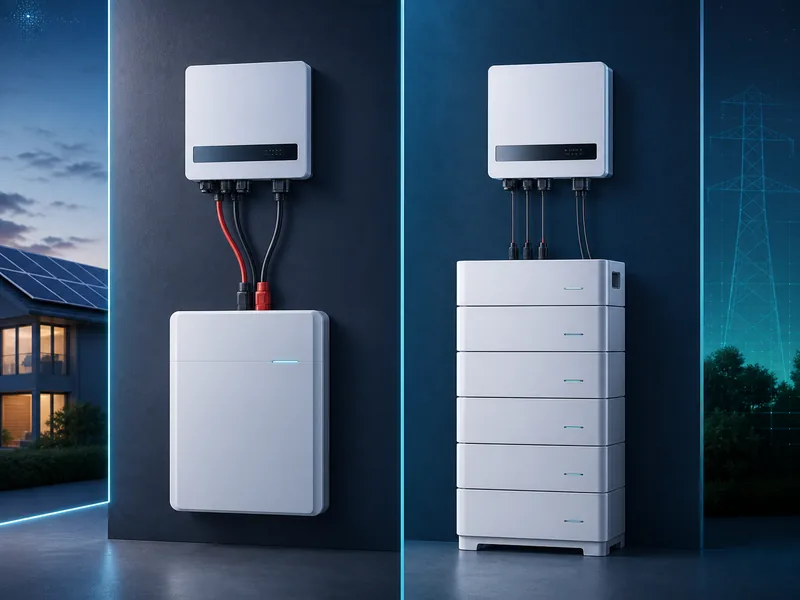
In residential and small-commercial energy storage, “low voltage” commonly describes battery platforms around 48 V or 51.2 V nominal. “High voltage” usually describes a purpose-designed series stack operating at a substantially higher DC voltage, often across a range of hundreds of volts. These are market categories, not universal legal definitions.
Official product families illustrate the distinction. GoodWe lists its Lynx U G3 low-voltage battery at 51.2 V nominal. Its Lynx Home F high-voltage series uses stackable modules, with total stack voltage changing as modules are added. These examples show two architectures from one manufacturer; they are not universal specifications for all battery systems.
| Factor | Low-voltage battery system | High-voltage battery system |
|---|---|---|
| Typical market architecture | Often a 48 V or 51.2 V-class battery bank | Purpose-designed series stack operating at a higher DC voltage |
| Current at the same DC power | Higher | Lower |
| Common expansion method | Additional supported modules in parallel | Additional supported modules in series within a stack; some systems also support parallel stacks |
| Inverter requirement | Inverter with the correct low-voltage battery input | Inverter with the correct high-voltage battery input and operating window |
| Battery control | BMS in each module or bank, depending on design | Usually coordinated stack control with a BMS/BCU and switching or pre-charge functions |
| Main design pressure | High DC current, cable size, busbars and current sharing | Voltage window, series configuration, isolation, controlled startup and shock protection |
The label alone is insufficient. An installer still needs the minimum and maximum battery voltage, permitted current, communication protocol, firmware requirements and supported number of modules.
Why Does Battery Voltage Change Current and Cable Requirements?
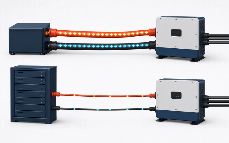
For approximately the same DC power, increasing voltage reduces current. The basic relationship is:
Power ≈ Voltage × Current
Ignoring conversion losses, a 10 kW DC load would require approximately:
- 195 A at 51.2 V: 10,000 W ÷ 51.2 V ≈ 195.3 A
- 25 A at 400 V: 10,000 W ÷ 400 V = 25 A
This does not mean either example is a suitable real product configuration. It demonstrates why low-voltage systems can require substantial conductors, terminals, fuses, disconnects and busbars at higher power.
Victron Energy’s technical guide on current, cable resistance and voltage drop explains that higher current increases voltage drop and heat in resistive connections. Cable loss follows P = I²R, so current has a squared effect when resistance remains constant.
Lower current can reduce conductor losses and ease some current-handling requirements, but it does not make a high-voltage system automatically more efficient overall. Battery topology, inverter power stage, conversion path, standby consumption, temperature and operating point all affect system efficiency. Compare tested system data under equivalent conditions rather than relying on voltage-class marketing.
Cable and protection selection must follow the equipment manual, fault-current assessment and applicable installation rules. The calculation above is not a cable-sizing instruction.
Which Architecture Fits the Application?
The application should determine the architecture. Start with required power, energy, inverter type, installation environment, service model and future expansion—not with a belief that one voltage class is more advanced.
When a low-voltage battery may be practical
A low-voltage platform may fit when:
- the selected inverter uses a 48 V or 51.2 V-class battery input;
- the project is residential backup, off-grid or a modest solar self-consumption system;
- installers already support the platform and its commissioning process;
- modular parallel expansion is valuable;
- local replacement and service benefit from standalone modules;
- cable runs can remain short and the required current can be managed correctly.
The main constraint is often current. A battery may contain enough kWh but still be unable to supply the inverter’s required continuous power. Adding parallel modules may increase available current in some systems, but only within the manufacturer’s supported topology and bank limits.
When a high-voltage battery may be practical
A high-voltage platform may fit when:
- the selected hybrid inverter is designed for a high-voltage battery;
- higher system power would create difficult current levels on a low-voltage DC bus;
- the project benefits from a matched, integrated inverter-and-stack architecture;
- the supported series stack provides the required energy and operating-voltage window;
- trained installers can follow the required isolation, startup and commissioning procedures;
- expansion can be planned within the platform’s approved module and stack rules.
High voltage is not reserved for commercial projects, and low voltage is not limited to small homes. Manufacturers now offer both architectures across a wide power range. The exact system design matters more than a general market label.
| Project question | Why it matters |
|---|---|
| What inverter has already been selected? | Its battery input architecture may determine LV or HV before the battery is considered. |
| What continuous and surge power must the battery support? | Power establishes the current demand at the actual operating voltage. |
| How much usable energy is required? | kWh determines duration; it does not replace the power check. |
| Is the installation a retrofit? | Existing inverter, wiring, protection and available space may constrain the choice. |
| How will the system expand? | LV parallel modules and HV series stacks have different configuration rules. |
| Who will commission and service it? | HV systems and complex multi-module banks require platform-specific competence. |
How Does Inverter Compatibility Affect the Choice?
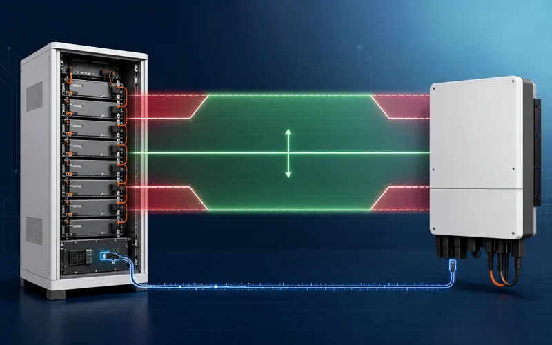
The battery and inverter must use the same voltage architecture, but voltage class is only the first compatibility gate. A low-voltage battery cannot be connected to a high-voltage-only battery input, and a high-voltage stack cannot be connected to a 48 V-class inverter.
For either architecture, verify:
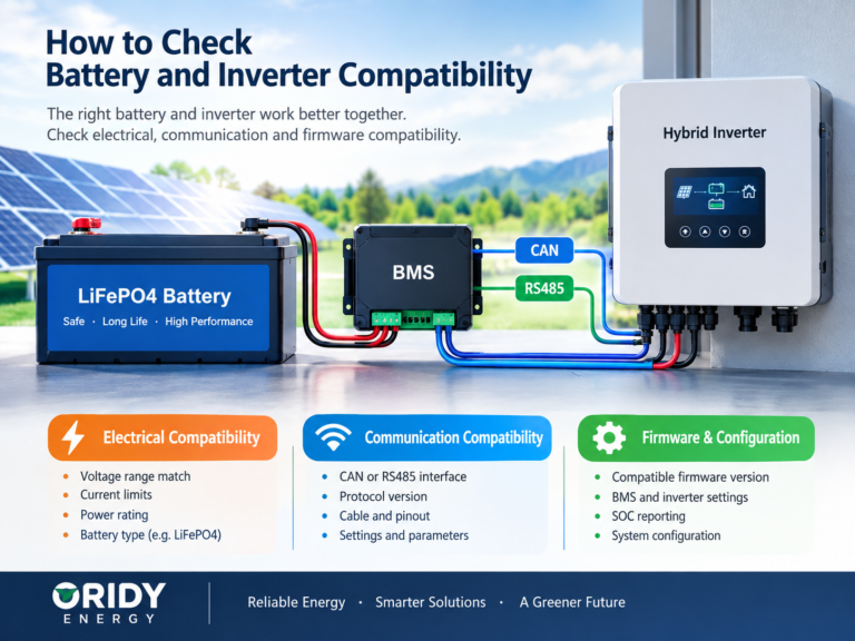
- Complete operating-voltage window: Compare the battery’s minimum and maximum operating voltage with the inverter’s permitted battery range, not only nominal voltage.
- Charge and discharge current: Confirm continuous limits, peak duration, temperature or SOC derating, and whether ratings apply per module, stack or complete bank.
- Power capability: Check whether the battery bank can support the intended inverter power at the lowest relevant operating voltage.
- Communication protocol: CAN or RS485 connector presence does not prove that the BMS and inverter exchange compatible messages.
- Cable and pinout: Matching RJ45-style sockets do not guarantee matching pins or electrical interfaces.
- Firmware: Record supported battery and inverter firmware versions and how changes are controlled.
- Functions tested: Verify SOC reporting, dynamic current limits, temperature response, alarms, shutdown, restart and recovery.
- Module configuration: Confirm minimum and maximum modules, master/follower or BCU requirements, addressing and termination.
Manufacturer compatibility documents should be treated as configuration-controlled evidence. SMA’s approved-battery technical information, for example, identifies supported battery systems and firmware conditions rather than treating “high voltage” as sufficient proof of compatibility. BYD likewise publishes separate operating documents and compatible-inverter lists for its battery families.
If you are checking a project combination, send ORIDY ENERGY the exact inverter model and regional variant, battery model, system voltage, firmware versions, required power and planned module count. These inputs are more useful than a brand-level request for a “compatible battery.”
How Do Capacity and Power Differ in LV and HV Systems?
Energy capacity is measured in kWh. Power is measured in kW. Voltage architecture changes how current contributes to power, but it does not remove the need to verify both values.
Consider a nominal 51.2 V, 100 Ah low-voltage battery:
Nominal energy = 51.2 V × 100 Ah ÷ 1,000 = 5.12 kWh
If its verified continuous discharge limit were 100 A, its approximate nominal DC power at 51.2 V would be:
51.2 V × 100 A = 5.12 kW DC
The example uses assumed ratings for calculation only. Real output changes with operating voltage, BMS limits, temperature, SOC, inverter efficiency and product-specific derating.
In a purpose-designed high-voltage stack, adding identical series modules raises total voltage and energy while the same current flows through the series string. That can increase stack power without the very high current of a 51.2 V bank. However, the BMS/BCU, contactors, inverter input and supported stack configuration still set the actual limits.
Do not compare an LV module’s ampere-hour rating directly with an HV stack’s ampere-hour rating. Compare usable kWh, continuous kW, peak capability and test conditions at the complete-system level.
How Do Expansion Rules Differ?
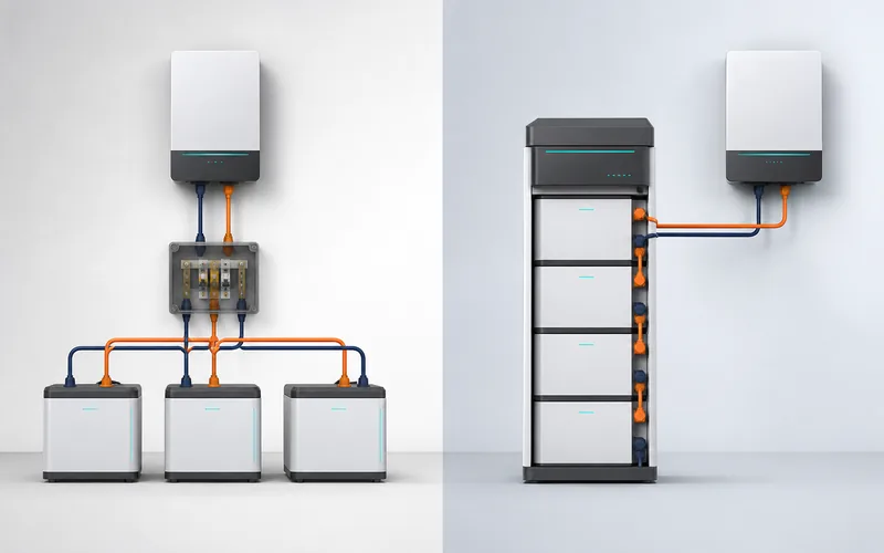
Low-voltage systems often expand through parallel modules, while high-voltage systems often expand by adding series modules to a supported stack. Neither method is universal, and neither permits arbitrary mixing.
| Expansion check | Low-voltage bank | High-voltage stack |
|---|---|---|
| Electrical topology | Usually parallel | Usually series within one controlled stack |
| Voltage effect | Bank voltage remains broadly similar | Stack voltage increases as series modules are added |
| Current effect | Supported parallel modules may share current | Series-string current passes through every module |
| Control | Module addressing or master/follower logic may be required | BMS/BCU must recognize the exact stack and module sequence |
| Typical restriction | Maximum parallel count, equal cable paths, firmware and current sharing | Minimum/maximum series modules, voltage window, module order and pre-charge procedure |
| Later expansion | May require matched model, firmware, SOC and age rules | May require approved module revision, SOC preparation and recommissioning |
Before promising future expansion, obtain written answers to these questions:
- What is the minimum and maximum supported module count?
- Can multiple complete stacks be paralleled?
- Must all modules have the same model, hardware and firmware?
- Are there limits on adding new modules to an older bank?
- What SOC preparation is required before connection?
- Are new cables, busbars, protection devices or communication terminators required?
- Does the inverter impose a lower limit than the battery platform?
“Expandable” is not a complete specification. Distributors should keep configuration records by model and revision so that sales promises remain supportable after the first shipment.
What Changes for Installation and Safety?
Both architectures store substantial energy and require professional design. Low voltage does not mean low risk: a 48 V-class bank can deliver very high fault current, and poor terminations can overheat or arc. High-voltage DC adds greater electric-shock and isolation risk and may require controlled contactors, pre-charge, interlocks and manufacturer-defined commissioning steps.
For either system, confirm:
- DC overcurrent protection and isolation;
- conductor size, insulation rating, length and termination method;
- prospective fault current and equipment interrupting ratings;
- grounding or earthing arrangement as required by the product and local rules;
- enclosure location, clearances, ventilation and environmental limits;
- lifting, mounting and service access;
- emergency shutdown and restart procedure;
- labeling and access control;
- installer qualifications and local inspection requirements.
Never use a battery’s enclosure rating or a generic certification logo as proof that a proposed installation is acceptable. Product documentation, local requirements and the complete system design must be evaluated together. Certification requirements and available documentation depend on the selected model and target market.
What Should Buyers Confirm Before Ordering?
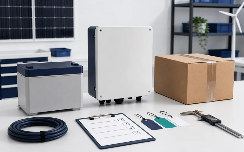
An RFQ should define the system job and the exact evidence required. Asking only for battery voltage, capacity and price leaves major compatibility and service risks unresolved.
| RFQ field | Information to request |
|---|---|
| Application | Backup, solar self-consumption, off-grid, residential, small commercial or another defined use |
| Inverter | Exact brand, model, regional variant, phase and firmware |
| Battery architecture | LV or HV, nominal voltage and complete operating range |
| Energy | Nominal and usable kWh, permitted DoD and test conditions |
| Power | Continuous and peak charge/discharge current, duration and derating conditions |
| BMS communication | Protocol profile, CAN/RS485 interface, pinout, cable, settings and functions supported |
| Expansion | Minimum and maximum modules, topology, mixed-age rules and parallel-stack support |
| Installation | Indoor/outdoor conditions, temperature range, clearances, mounting, cable and protection requirements |
| Documentation | Datasheet, manual, wiring diagram, compatibility record, test reports and model-specific compliance documents required for the destination |
| Version control | Battery hardware, BMS, firmware and change-notification process |
| Quality plan | Sample validation, pre-shipment checks, serial traceability and incoming inspection |
| Commercial scope | Quantity, packaging, OEM/ODM requirements, destination and requested CIF or DDP quotation basis |
Validate a representative system before a bulk order
- Match the datasheet, label, manual, quotation and documentation to the same model and revision.
- Test the exact battery, inverter, communication cable and firmware combination.
- Charge and discharge across relevant operating conditions without exceeding documented limits.
- Verify SOC, current-limit updates, temperature behavior, alarms, controlled shutdown and restart.
- Test the planned multi-module configuration, not only one battery.
- Record settings, firmware, wiring, observations and acceptance criteria.
- Define technical-support ownership, diagnostic evidence and change control before shipment.
For sourcing projects, ORIDY ENERGY can support OEM, ODM, CIF and DDP discussions where appropriate. The actual configuration, documentation, quantity, price, lead time, logistics responsibilities and destination requirements must be confirmed for the selected model and quotation.
If you are preparing an RFQ, send the intended application, inverter model, required usable energy, continuous and surge power, preferred LV or HV architecture, expansion plan, quantity and destination market. ORIDY ENERGY can help organize the technical comparison and sourcing questions before commercial terms are finalized.
A Practical Low Voltage vs High Voltage Battery Decision Process
Use this sequence before choosing the product family:
- Define the load: Record continuous power, surge power and required backup duration.
- Select or confirm the inverter: Identify phase, power rating, battery-input architecture and operating range.
- Calculate energy and current: Estimate usable kWh and DC current across the relevant battery-voltage window.
- Verify compatibility: Confirm protocol, cable, settings, firmware and tested functions for exact models.
- Plan installation and expansion: Check protection, conductor routing, module count, service access and future additions.
- Validate procurement evidence: Review model-linked documents and test a representative system before scaling.
The best architecture is the one that meets these requirements with a supported configuration and a serviceable supply path. Voltage class should make the engineering work—not replace it.
For a low voltage vs high voltage battery review, send ORIDY ENERGY the inverter brand and exact model, battery-voltage architecture, required kWh and kW, application, expected quantity, expansion requirements and destination market. This gives the technical and sourcing teams enough information to compare appropriate configurations without making unsupported compatibility assumptions.