Diagnose Slow AC EV Charging: An Installer’s Troubleshooting Guide
To diagnose slow AC EV charging, establish what the exact vehicle and installation should deliver, then compare that expectation with a recorded session. Check vehicle AC acceptance, operating phases, current settings and active controls together. A delayed start, a stable low rate and a rate that falls during charging require different evidence; none alone establishes a defective charger.
The installer’s immediate decision is whether the session reflects a documented limit, a configuration issue or an unresolved fault. That distinction determines whether the next action belongs with the vehicle owner, commissioning team, electrical contractor, charging-platform operator or equipment supplier.
This guide follows that diagnostic decision. For equipment sizing after the limitation has been established, use the separate 7kW, 11kW and 22kW EV charger selection guide.
Diagnose slow AC EV charging: start with the symptom.
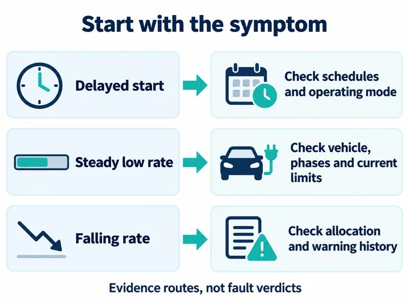
Replace “the charger is slow” with a specific observation. Record when the vehicle was connected, when charging actually began, whether the displayed power remained steady and whether any warning appeared. Preserve the original settings and logs before making changes.
| Observed symptom | Evidence to collect first | Next diagnostic question |
|---|---|---|
| Connected but waiting | Vehicle and charger schedules, operating mode, status message and timestamps | Is charging intentionally delayed or paused? |
| Consistently below the expected rate | Vehicle acceptance documentation, current settings, active phases and commissioned limit | Does the expectation match this vehicle and installation? |
| Power changes with site activity | Site-load readings, other sessions and controller allocation at matching timestamps | Is a documented control function changing the allocation? |
| Power falls after charging starts | Temperature indications, alarms, current and operating-state history | Does the equipment report a reason for reducing current? |
| Problem occurs with one combination | Vehicle, cable and charge-point identities plus comparable test records | Which changed component or condition follows the symptom? |
These are investigation routes, not fault verdicts. More than one route may apply to the same session.
Create a common record for the vehicle display, charge-point interface and management platform. Note whether each value is instantaneous, averaged or accumulated, and ask the relevant supplier to explain any unclear measurement boundary. Do not assume that two screens labelled “charging power” report the same quantity.
The zappi operation and installation manual illustrates useful diagnostic visibility: charging watts, AC current, voltage, active phases, pilot PWM, internal temperature and session energy. Those fields belong to the documented equipment; another charger may expose fewer readings. Record unavailable information explicitly rather than estimating it from the headline power.
Establish the vehicle’s documented AC acceptance
Begin with the exact vehicle variant and its AC charging documentation. Tesla’s Wall Connector guidance directs users to vehicle-specific maximum-current information, reinforcing that the charging equipment’s rating alone does not establish the vehicle’s expected rate.
Request the model year, destination-market variant, onboard-charger specification and supported supply arrangements. Record the vehicle’s current setting and any charging message shown during the affected session. A brand name or model family is insufficient when the applicable hardware and regional documentation have not been identified.
Keep two questions separate:
- What does the vehicle documentation permit? Obtain its AC maximum, supported phases and applicable current limits.
- What was the vehicle doing in this session? Record its selected current, charge target, operating state and warnings.
If battery temperature, state of charge or an auxiliary load is proposed as the explanation, request vehicle-specific evidence. There is no universal state-of-charge threshold or percentage reduction established by the sources used here.
A useful service conclusion would identify the applicable vehicle specification and show how the recorded session relates to it. “The car cannot take more” is incomplete without that documentation. Equally, a low reading should not become a charger replacement request before the vehicle limit is known.
Find the active limit before judging charger power
A charger nameplate describes equipment capability, not the power every connected vehicle must receive. Establish the phases actually accepted by the vehicle and available through the installation and cable first. Then compare current limits on that same phase basis. A three-phase supply cannot make a single-phase onboard charger use three phases.
For a stable session, a useful diagnostic ceiling is the lowest applicable limit among the vehicle’s AC acceptance, its selected current, the EVSE capability, the cable rating, the approved circuit charging allowance, the commissioned charger maximum and the controller’s current allocation. This is a troubleshooting model, not a guaranteed output equation: thermal restrictions, faults or vehicle operating conditions can reduce actual draw further.
The circuit allowance must come from the approved installation design and commissioning record. A protective device’s marked rating is not automatically the continuous charging current. Tesla’s regional installation table separates breaker rating from programmable output and explicitly says vehicle acceptance also determines the actual rate. Apply the relevant local rules and exact model documentation rather than importing that table globally.
Identify which ceiling is active before proposing a change. If the controller allows 10 A while every fixed limit permits at least 16 A, increasing a charger setting above 16 A cannot remove the 10 A allocation. If the vehicle accepts only one phase, replacing a working three-phase charger cannot by itself create three-phase vehicle acceptance. Those conclusions prevent an unnecessary equipment replacement.
Check supply phases and current together
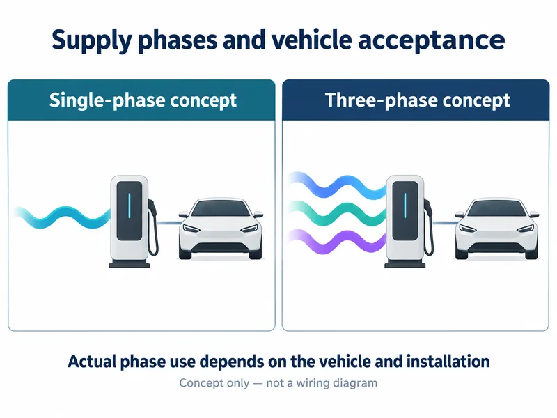
A current value without its supply arrangement is an incomplete diagnostic record. Establish whether the installation is commissioned for single-phase or three-phase operation, which phases the vehicle supports, and which phases the charge point reports as active during charging.
Manufacturer charging tables must remain scoped to the exact vehicle and market. The regional Volvo EC40 charging-times page illustrates different kW entries at the same 16 A current. Use the equations below to interpret the actual phase arrangement; do not generalise Volvo’s entries to another vehicle.
For the affected installation, collect the following information side by side:
- The recorded supply arrangement and charge-point commissioning configuration.
- The vehicle’s documented acceptance for that arrangement.
- Available voltage and current readings, with phase identification and timestamps.
- The detachable cable’s identity, documented current rating and phase capability, where applicable.
- Any phase-related status or fault indication explained by the equipment manual.
Do not diagnose a missing phase solely because the displayed power resembles a familiar fraction of a nameplate rating. First establish the documented operating arrangement, then investigate any discrepancy through the manufacturer’s procedure. Unexpected phase telemetry is evidence to examine, not permission to improvise wiring changes.
If electrical measurements or enclosure access are required, assign them to a suitably qualified electrical professional using the applicable installation and service procedures. This diagnostic guide does not prescribe conductor sizes, protective-device ratings or live terminal tests.
Calculate the expected AC input, then compare the session
Use voltage and current from the same charging session, with their phase definitions. For single-phase AC, input real power in kW is V × I × PF ÷ 1,000. For a balanced three-phase load, use √3 × U × I × PF ÷ 1,000. V is phase-to-neutral voltage, U is line-to-line voltage, I is RMS current per active phase and PF is power factor.
Schneider’s Electrical Installation Guide gives the corresponding single-phase and balanced three-phase apparent-power relationships. Its power-factor guidance distinguishes true PF from displacement cos φ when distortion is present. The examples below assume PF = 1, stable nominal voltage and the stated active phases. They are calculated AC-input reference points, not battery charging guarantees or product specifications.
| Assumed operating arrangement | Calculation | Nominal AC input |
|---|---|---|
| One phase, 230 V, 16 A | 230 × 16 ÷ 1,000 | 3.68 kW, about 3.7 kW |
| One phase, 230 V, 32 A | 230 × 32 ÷ 1,000 | 7.36 kW, about 7.4 kW |
| Balanced three phases, 400 V line-to-line, 16 A each | √3 × 400 × 16 ÷ 1,000 | 11.09 kW, about 11 kW |
Do not substitute 400 V into the single-phase phase-to-neutral equation for a nominal 230/400 V supply, or treat 16 A per phase as 48 A in the three-phase equation. For unbalanced currents, use the measured real power on each phase and add it; one average current may hide the limitation. A lower actual voltage or PF changes the kW result even if current is unchanged.
Worked case: a lower rate that matches load management
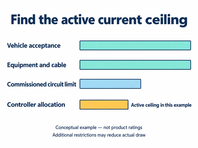
Assume a hypothetical installation has a three-phase-capable 32 A-per-phase EVSE and cable, but the vehicle accepts only one phase up to 32 A. Its selected current permits 32 A. The approved circuit charging allowance and commissioned EVSE maximum are both 16 A per phase. At the complaint timestamp, the controller allocates 10 A on the phase used by this vehicle. These values are illustrative inputs, not specifications of a named product.
The controller’s 10 A allocation is below every other applicable limit, so it sets the current ceiling for this session. At 230 V and PF = 1, expected input at that ceiling is 230 × 10 ÷ 1,000 = 2.30 kW. A stable reading near 10 A and 2.3 kW therefore fits the allocation, despite the EVSE’s larger nameplate. Verify the controller’s input and policy rather than declaring the charger defective.
If the allocation later rises to 16 A, the fixed installation limit becomes active: the reference increases to 3.68 kW, not 7.36 kW or 11 kW. If allocation permits 16 A but draw remains 10 A, inspect the vehicle setting and operating messages, cable limits and EVSE restrictions next. Do not increase the circuit allowance to force a different outcome.
These comparisons concern AC input at the stated measurement boundary. Onboard conversion losses and vehicle auxiliary consumption mean battery energy gain is a different quantity; no universal efficiency percentage is assumed. Confirm whether the displayed value is AC input, battery-side power, a session average or an instantaneous reading before treating a difference as a fault.
Trace the settings that control the session
Record both the installation ceiling and the control state at the moment of the complaint. A configured maximum and an active session allocation answer different questions.
Tesla’s power-management documentation describes fixed installation limits, dynamic adjustment with building consumption and allocation between grouped Wall Connectors. These documented functions show why changing session power can be intentional. Their availability, metering requirements and commissioning details must not be assumed for another product.
Save the commissioned installation limit and obtain the active controller allocation for the complaint timestamp. Compare those values with the vehicle and cable limits on the same phase basis.
Compare the offered current with the current actually drawn
Where supported, the control-pilot or equivalent telemetry describes available current; the current meter reports what the vehicle actually draws. myenergi’s PWM explanation documents that distinction for zappi. Obtain the exact model’s field definitions and conversion method rather than applying one brand’s PWM percentages to every EVSE.
If offered current and measured draw are both low, trace the charger configuration, controller allocation and any restriction status upstream. If the EVSE offers more than the vehicle draws, compare the vehicle’s documented phase/current acceptance and selected limit first, then its messages and comparable-session results. The gap narrows the investigation; it does not prove an onboard-charger fault or eliminate cable, communication or thermal problems.
For managed three-phase sites, inspect the phase that the vehicle actually loads. Spare capacity on two phases does not necessarily remove a restriction on the third. myenergi’s phase-rotation and CT guidance requires the physical phase, CT connection and configured phase mapping to agree. If they disagree, a controller may attribute a reading to the wrong phase and base its allocation on an incorrect view of available capacity. This is a diagnostic inference, not proof that any particular CT error always reduces charging.
Have the commissioning professional compare controller readings with suitable independent phase measurements and the wiring record. Check CT orientation, mapping, meter communication and any reported stale-data or fallback status against that model’s manual. For a load-managed session, check the available meter inputs and configured policy before accepting the allocation as explained.
The zappi manual specifically requires correct current-transformer configuration and describes ECO/ECO+ behaviour that adjusts or pauses charging with available surplus. For a solar-controlled installation, therefore, record the selected mode, surplus indication and pause reason alongside the charging readings. Do not import zappi menu names or behaviour into another charger’s diagnosis.
Check timing before investigating low active power
Ask whether “slow” means charging started late or charging remained low after it started. Capture vehicle schedules, charger schedules and any platform schedule, then obtain the model’s documented precedence rules before changing them.
For covered private charge points sold in Great Britain, OPSS smart charge-point guidance describes default off-peak hours and randomised delay functionality. This provides a specific reason to investigate timing separately from active-session power. The guidance excludes Northern Ireland and public charge points from that scope; it is not a worldwide scheduling rule.
Investigate falling power with the warning history
When a session begins as expected and later slows, retain the sequence of readings. A single screenshot taken after the reduction cannot show which event came first.
Tesla’s thermal-monitoring documentation describes temperature monitoring at multiple locations and possible current reduction in warmer conditions. On equipment with documented thermal reduction, a corresponding temperature indication or warning warrants the model’s diagnostic procedure.
Record ambient conditions, the initial and reduced current, elapsed time, reported temperature where available and the complete warning text. Include whether the event repeats under comparable conditions. Ask the supplier which measured location and threshold apply to the exact model; do not substitute a generic temperature limit.
A thermal indication does not, by itself, identify a loose terminal, damaged cable, unsuitable mounting location or vehicle fault. Those conclusions require the appropriate inspection and supporting evidence. Follow the documented stop-use and service instructions for the warning, and preserve the event record before any manufacturer-directed reset.
If no thermal indication is available, keep the diagnosis open. Compare the reduction timestamp with controller allocations, vehicle messages and site activity.
Use controlled comparisons to narrow the cause
Comparison testing is most useful when the changed variable is identified and the surrounding conditions are recorded. Treat the result as evidence that narrows the investigation, not automatic proof that a particular component is defective.
In its slow-charging troubleshooting guidance, myenergi describes comparison tests using another suitable charger or vehicle. Preserve model-specific conditions and seek the relevant supplier’s procedure.
- Save the baseline. Record vehicle identity, charge-point model and firmware, cable, operating mode, settings, warnings and session readings.
- Agree the comparison. Use a manufacturer-supported procedure and a charging arrangement documented as suitable for the vehicle.
- Change one practical variable. For example, test the same vehicle at another suitable AC charge point. Record any unavoidable change in cable, supply or control conditions.
- Compare equivalent evidence. Check active-session readings and documented limits, rather than comparing one session’s peak with another session’s average.
- Return the result to the responsible supplier. State what changed, what stayed comparable and what remains unknown.
If the symptom follows the vehicle across suitable AC installations under comparable conditions, vehicle-side investigation becomes a stronger next step. If it appears only at one charge point, examine that installation’s configuration and conditions. Neither result eliminates all other explanations.
A cable substitution should use a documented compatible cable and the equipment’s normal connection procedure. A second vehicle is useful only if its acceptance and operating conditions are also recorded. Otherwise, different results may simply reflect different test requirements.
Do not raise installation or protective limits as an experiment. A proposed increase belongs in an electrical design and commissioning review, not an attempt to make the displayed number match a label.
Turn the readings into the next diagnostic action
Compare the session with its calculated and documented ceiling, not only the nameplate. Use time-aligned active-phase, offered-current, drawn-current and real-power readings. The following patterns prioritise checks; they do not identify a failed component by themselves.
| Observed pattern | What it suggests | Check next |
|---|---|---|
| One active phase at about 16 A and 3.7 kW on nominal 230 V | Consistent with one-phase 16 A input under the stated PF assumption | Vehicle phase acceptance and the active 16 A ceiling; do not infer a missing phase from kW alone |
| Three phases near 16 A each, around 11 kW, below a larger nameplate | A 16 A-per-phase limit may be active | Vehicle acceptance, commissioned current and controller allocation before changing equipment |
| Controller allocation, offered current and draw fall together as building load rises | Intentional dynamic limitation is plausible | Time-aligned meter inputs, configured site policy and phase mapping |
| Offer stays above draw while power remains low | The EVSE’s offered-current ceiling alone does not explain the shortfall | Vehicle limits and messages, actual phase use, cable documentation, restrictions and controlled comparisons |
| Current is as expected but real power is lower than the nominal calculation | Voltage, PF or measurement boundary may explain the difference | Simultaneous voltage/PF and real-power readings; distinguish AC input from battery-side display |
| Documented three-phase operation is expected but current appears on only one phase | The phase pattern needs investigation | Vehicle capability, operating mode, cable phase capability, commissioning and fault history through the approved service procedure |
For example, a high nameplate plus a 10 A offer and 10 A draw points first to the source of the offer. A 16 A offer with 10 A draw points first to why the vehicle is not drawing the available current. If all documented ceilings permit 16 A but the readings remain unexplained, retain that discrepancy for service support; do not invent a normal-loss percentage to close the case.
After an authorised correction, repeat the baseline under comparable conditions. Record the predicted change and the observed result. A configuration diagnosis is stronger when the corrected limit and measured behaviour agree; replacing several parts at once makes the cause harder to establish.
Need help reviewing an EV charging configuration or sourcing suitable equipment? ORIDY ENERGY works with qualified Chinese manufacturing partners for EV charging and energy-storage solutions. Send us your project requirements →
Close the case with evidence the supplier can use
Finish the visit with a supported finding or a clearly bounded unresolved question. State the expected behaviour, the observed behaviour, the evidence connecting them and the responsible next action.
| Finding | Evidence needed | Appropriate next action |
|---|---|---|
| Documented vehicle limit | Exact vehicle specification and matching session record | Explain the operating expectation and retain the record |
| Intentional control allocation | Controller policy and time-aligned allocation history | Have the operator confirm that policy matches the site requirement |
| Configuration discrepancy | Saved settings compared with the approved commissioning record | Assign correction and retesting to the authorised commissioning team |
| Equipment warning or unexplained reduction | Warning history, firmware, conditions and comparison results | Escalate through the relevant manufacturer’s service procedure |
| Insufficient evidence | A list of missing specifications or readings | Request those items before recommending replacement |
The escalation record should include exact vehicle and charger identities, firmware versions, cable details, country, supply arrangement, commissioned limits, operating modes, timestamps, available phase/current/voltage readings, alarms and completed comparisons. Include the source of the expected rate. This makes the unresolved question specific enough for a technical support team to answer.
For distributors considering replacement or repeat supply, ask prospective suppliers to demonstrate diagnostic access before ordering: available telemetry, event-log export, configuration backup, explanation of active limits, supported meter/controller combinations and firmware support. Request the model-specific service process and the evidence required for a warranty claim; do not assume coverage or replacement terms.
The public IEC 61851-1:2017 catalogue description covers EV supply equipment operating conditions, its connection with the vehicle and electrical safety. That scope does not establish a particular product’s certification or provide a complete field-test procedure. Use the exact equipment documentation and the installation’s applicable requirements for corrective work.
ORIDY ENERGY is a China-based renewable-energy supply-chain, sourcing and technical-coordination partner.
Planning an EV charging project? Share your destination market, charger type, required power, quantity and project requirements.
ORIDY ENERGY can help coordinate suitable product options, supplier checks and technical configurations for your EV charging project.