
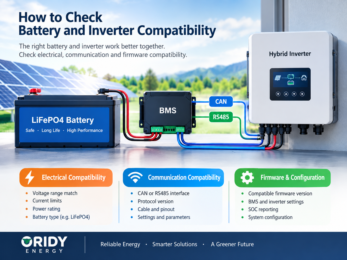
How to Check Battery and Inverter Compatibility
Battery and inverter compatibility can appear correct on paper and still fail during commissioning. The nominal voltage may look correct, the cable may fit, and both datasheets may mention CAN or RS485. Yet the inverter may show the wrong state of charge, refuse to charge, restrict output, or report a communication fault.
Battery and inverter compatibility requires agreement at three levels: the electrical operating window, the charge and discharge limits, and the control system. For lithium batteries, the control layer normally includes the battery management system (BMS), communication interface, application protocol, cable pinout, device settings, and firmware versions. Future expansion must also be supported as a complete system—not assumed from the presence of extra terminals.
The most reliable evidence is an up-to-date compatibility statement for the exact battery and inverter models, supported by current manuals and a controlled commissioning test. A brand name, nominal voltage, or matching socket is not enough.
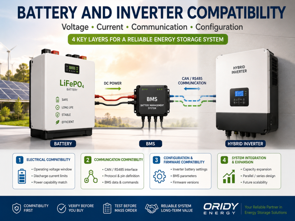
What Does Compatibility Actually Mean?
Compatible equipment can operate across the intended battery state-of-charge range without exceeding the limits of the battery, inverter, BMS, conductors, protection devices, or communication system. Compatibility is therefore a system condition, not a single specification.
Four questions provide a useful first screen:
- Does the battery’s real operating-voltage window fit inside the inverter’s permitted battery-voltage range?
- Can the battery safely accept the inverter’s possible charging current and supply the required discharge current?
- Can the BMS and inverter exchange the correct messages using the same interface, protocol, pinout, settings, and supported firmware?
- Is the proposed number and arrangement of battery modules explicitly supported?
| Compatibility layer | What must match | Typical consequence if it does not |
|---|---|---|
| Electrical | Battery operating voltage, polarity, current, power path, protection | No start, shutdown, derating, or equipment damage |
| Communication | Interface, protocol profile, bitrate or baud rate, pinout, addressing, device roles | Communication alarm, missing SOC, incorrect limits |
| Software | Battery and inverter firmware, selected battery profile, configuration | Intermittent operation, incorrect data, lost features |
| System architecture | Low- or high-voltage design, master/slave arrangement, supported module count | Failed commissioning or unsafe expansion |
| Market and installation | Approved equipment combinations, manuals, applicable codes and grid requirements | Permit, warranty, service, or interconnection problems |
An electrically workable combination is not necessarily a manufacturer-supported combination. That distinction matters to EPC contractors and distributors because technical operation, warranty acceptance, regulatory acceptance, and after-sales responsibility are separate questions.
Why Battery and Inverter Compatibility Goes Beyond Voltage
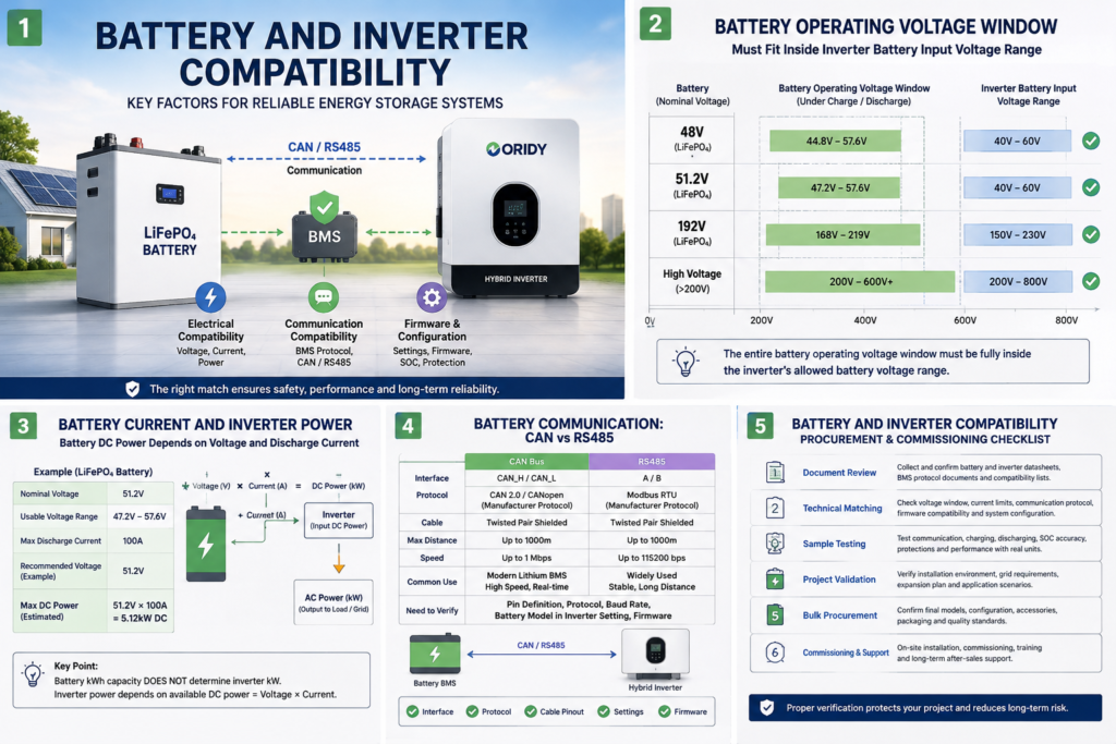
The battery’s full operating-voltage range must remain within the inverter’s battery input window under charging, discharging, temperature changes, and load. Matching “48 V” to “48 V” is only a preliminary label check.
Nominal voltage is not the operating window
Nominal voltage is a convenient system description. It is not the maximum charging voltage or the minimum voltage at which a battery should continue discharging. A battery pack’s voltage changes with cell chemistry, series cell count, state of charge, temperature, current, and BMS limits.
Compare at least these battery values with the exact inverter manual:
- nominal voltage;
- normal operating-voltage range;
- recommended and absolute charge-voltage limits;
- discharge cut-off or BMS low-voltage limit;
- voltage under expected load;
- inverter start-up voltage, operating range, charge target, and low-voltage shutdown behavior.
The battery’s BMS protection thresholds should not become the inverter’s routine control method. If the inverter repeatedly pushes the battery to a BMS over-voltage or under-voltage trip, the pair is not correctly coordinated even if it restarts afterward.
Low-voltage and high-voltage architectures are not interchangeable
A low-voltage battery system generally operates at much lower DC voltage and consequently higher current for the same power. A high-voltage battery normally uses series-connected modules, a master battery controller, contactors, and a compatible high-voltage inverter input. One architecture cannot be substituted for the other merely by changing a cable.
The same power relationship explains why this matters:
DC power ≈ battery voltage × battery current
For an illustrative 5 kW DC requirement, current would be about 104 A at 48 V but about 12.5 A at 400 V. These simplified figures exclude conversion losses and voltage variation; they demonstrate the relationship rather than specify a product. Low voltage is not inferior, and high voltage is not automatically better. Each requires the appropriate inverter, protection, conductor design, installation method, and battery-control architecture.
Check transient conditions, not only steady-state values
Battery voltage can sag under a high load and rise during charging. Cold conditions can also affect permitted charging current and usable operating behavior. The compatibility review should therefore consider the worst intended operating points, including inverter surge demand and battery BMS limits, rather than comparing two nominal figures in a quotation.
How Do Charge and Discharge Current Affect the Match?
The inverter must not charge faster than the battery can safely accept, and the battery must be able to supply the inverter’s required DC current. Energy capacity in kilowatt-hours does not establish either capability.
Discharge current can limit inverter output
Consider an example 51.2 V, 100 Ah battery with a stated continuous discharge limit of 100 A. Its nominal energy is:
51.2 V × 100 Ah ÷ 1,000 = 5.12 kWh
Its approximate DC power at 100 A and nominal voltage is:
51.2 V × 100 A = 5.12 kW DC
That does not guarantee 5.12 kW of continuous AC output. Actual capability depends on instantaneous battery voltage, inverter efficiency, temperature, duration, cabling, parallel configuration, and any lower limit imposed by the cells or BMS. A 10 kWh battery could also have a current limit too low for a particular inverter. Capacity answers “how much energy”; current and voltage help answer “how much power now.”
For preliminary sizing:
Required battery current ≈ required AC power ÷ (battery voltage × assumed inverter efficiency)
The efficiency used here must be a documented value or a clearly stated design assumption. Final selection should use manufacturer instructions and design margin, not the simplified calculation alone.
Charge current needs a system-level limit
Review the inverter’s maximum battery charge current from all available energy sources. Depending on the inverter architecture and settings, PV and grid or generator charging may contribute to battery charging. The configured limit must remain within the battery manufacturer’s permitted conditions.
In a closed-loop system, the BMS may transmit a dynamic charge-current limit based on temperature, SOC, cell voltage, or a fault condition. The inverter must understand and obey that message. A fixed inverter setting is not a substitute for compatible BMS control when the system design requires closed-loop communication.
Parallel batteries do not justify casual current multiplication
Adding identical parallel modules may increase available energy and current, but the usable system limit is governed by the supported architecture. Battery sharing, cable resistance, fuse and busbar ratings, master BMS limits, inverter limits, and manufacturer rules all apply. Do not simply multiply a single module’s current rating without verifying how the complete bank is controlled and protected.
Why Do the BMS, CAN, and RS485 Matter?
The battery management system monitors and protects the battery. In a closed-loop energy-storage system, it also provides information and operating limits that the inverter uses to control charging and discharging.
Depending on the design, exchanged data may include:
- pack voltage and current;
- SOC and sometimes state of health;
- permitted charge voltage;
- charge-current limit;
- discharge-current limit;
- temperature;
- alarms, warnings, and stop requests;
- operating or contactor status.
The exact dataset and control behavior are product-specific. Never assume every BMS transmits every item.
CAN is not a universal battery language
Controller Area Network (CAN) defines lower-layer communication capabilities, but products still need compatible higher-layer message definitions. Two devices may both have a CAN transceiver and an RJ45-style port while using different identifiers, data fields, scaling, timing, bitrate, cable pinout, or control logic.
This is why “both products support CAN” does not prove compatibility. The exact battery protocol or inverter battery profile must be supported on both sides. The communication cable must also have the documented pinout; a familiar connector shell does not establish safe wiring.
RS485 is also an interface, not proof of interoperability
RS485 describes an electrical signaling interface. The application protocol carried over it may use a manufacturer-specific register map or another defined protocol. Successful communication can depend on baud rate, parity, device address, master/slave roles, register definitions, data format, cable pinout, and termination.
A battery’s RS485 service port may be intended for a monitoring tool or battery-to-battery networking rather than inverter control. Confirm the purpose of the exact port in the manual. Do not connect ports based only on their labels.
CAN versus RS485 is not the main purchasing decision
Neither interface is automatically the better choice for every energy-storage system. The practical question is which fully supported interface and protocol combination exists for the exact battery, inverter, and firmware versions. Procurement documents should name the interface and the supported protocol profile, not just request “CAN/RS485.”
| Item to verify | CAN example | RS485 example |
|---|---|---|
| Physical interface | Correct CAN transceiver and bus wiring | Correct differential interface and wiring |
| Communication settings | Bitrate and termination | Baud rate, parity, address, and termination |
| Application layer | Matching message IDs, definitions, scaling, timing | Matching command/register map, definitions, and roles |
| Cable | Exact documented pinout | Exact documented pinout |
| Product support | Exact battery and inverter models | Exact battery and inverter models |
| Software support | Approved firmware combination and profile | Approved firmware combination and profile |
If you already have an inverter model and a proposed battery, ORIDY ENERGY can help organise the voltage, current, protocol, cable, and firmware questions that should be confirmed before ordering. Send the exact model numbers rather than only the brand names.
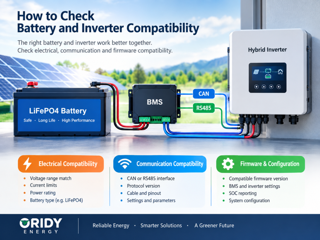
What Is Protocol Compatibility?
Protocol compatibility means that the battery and inverter interpret the same messages in the same way and respond with the required control behavior. A physical link can be active while application-level communication remains wrong.
A defensible compatibility confirmation should identify:
- exact battery model, BMS model or revision where relevant, and battery firmware;
- exact inverter model and inverter firmware;
- selected battery profile or protocol name in the inverter;
- interface and communication settings;
- cable part number or pin-to-pin definition;
- expected master and follower roles;
- messages or functions supported;
- any module-count or topology restrictions.
Examples of protocol mismatch symptoms include a communication alarm, an SOC value fixed at zero or 100%, an incorrect charge limit, unexplained derating, cycling between charge and stop states, or failure to close a high-voltage battery contactor. These symptoms can have other causes, so they are diagnostic clues rather than proof of one fault.
Open-loop and closed-loop operation are different claims
In open-loop operation, the inverter may be configured with fixed voltage and current settings while the battery BMS independently protects the pack. Some low-voltage products allow this when the battery manufacturer supplies appropriate settings. Other products—particularly some high-voltage inverter architectures—require closed-loop communication and will not support an unapproved open-loop battery.
Closed-loop operation allows the inverter to act on battery data and dynamic limits, but only when integration is correctly implemented. “It works in lead-acid mode” should not be presented as equivalent to approved lithium-battery compatibility. It can affect SOC-based functions, dynamic current control, fault coordination, warranty, and support.
Why Can SOC Communication Be Wrong?
The inverter’s displayed SOC is reliable only when the BMS estimate is credible and the communication path interprets it correctly. Voltage alone is often an inadequate substitute for an accurate lithium-battery SOC estimate, especially across a relatively flat voltage region.
SOC problems may arise from:
- an incorrect battery profile;
- incompatible message identifiers or register definitions;
- scaling or byte-order differences;
- outdated firmware;
- incorrect battery capacity configured in the system;
- an uncalibrated or drifting BMS estimate;
- the wrong master battery selected in a parallel bank;
- communication cabling, addressing, or termination faults;
- a battery that has not reached the conditions required for SOC synchronization.
During commissioning, compare the inverter display, battery display or service tool, measured pack voltage, and expected charge/discharge behavior. A plausible SOC number is not enough: verify that the inverter receives and follows the battery’s charge and discharge limits and responds correctly to warnings.
How Does Firmware Affect Compatibility?
Firmware forms part of the approved equipment combination. A battery model and inverter model that once passed integration testing may behave differently after one side changes its communication implementation, supported profile, alarm logic, or commissioning requirements.
Before a sample or bulk order, record the firmware versions used for compatibility evidence. Ask whether the tested combination requires a minimum, maximum, or specific version; how updates are delivered; whether field rollback is possible; and who owns integration support if an update breaks communication.
Avoid an automatic “update everything” response during troubleshooting. First check the current compatibility documentation and release instructions. Some upgrades must follow a defined sequence, and an unsupported version combination can create more uncertainty. Preserve the original versions, settings, event logs, and test results before changing software.
For distributors, firmware governance is also a stock-management issue. Two visually identical units from different production periods may not be equivalent if their hardware revisions or update paths differ. Version traceability should be part of incoming inspection and after-sales records.
Can Batteries Be Added in Parallel Later?
Parallel expansion is possible only when the battery system explicitly supports the proposed models, quantities, connection method, firmware, and commissioning procedure. Spare connectors or a “parallel capable” label do not answer the complete question.
Confirm these points before promising future expansion:
- maximum number of modules and total system capacity supported;
- whether modules must be the same model, capacity, chemistry, hardware revision, and firmware;
- permitted age or SOC difference when adding a module;
- master/follower addressing and communication topology;
- inter-battery and battery-to-inverter communication ports;
- equal-length power cables, busbar design, fusing, disconnects, and protection requirements;
- inverter maximum current and capacity settings;
- commissioning, balancing, pre-charge, and shutdown sequence;
- warranty treatment for mixed-age banks.
When batteries are paralleled, unequal cable resistance or different internal conditions can produce uneven current sharing. A new battery also has a different usage history from an older bank. The manufacturer may require the modules to be brought to a similar SOC or voltage before connection, or may restrict mixing revisions entirely. Follow the documented procedure and qualified electrical practice; do not connect energized batteries casually.
High-voltage expansion is commonly a different architecture. Modules may be placed in series within a controlled stack, while multiple stacks may require approved controllers or combiner equipment. Calling every multi-module system “parallel batteries” can therefore create a serious specification error.
A Procurement and Commissioning Workflow
The lowest-risk process moves from documented compatibility to a controlled sample test and then to repeatable bulk deployment. A compatibility logo sheet is useful evidence, but it should not be the only evidence.
1. Define the application
Provide the required inverter output, phase, backup loads, expected surge, battery energy, charging sources, environmental conditions, expansion plan, destination market, and intended operating modes. Compatibility cannot be assessed accurately without the system duty.
2. Collect exact documents
Request current datasheets and installation manuals for both products, the battery compatibility list, the communication cable definition, firmware requirements, and commissioning instructions. Check publication or revision dates. A list that names only a brand without exact models is weak evidence.
3. Build a compatibility record
Record the following in the RFQ or technical schedule:
| RFQ field | Information required |
|---|---|
| Battery identity | Brand, exact model, BMS or hardware revision where relevant |
| Inverter identity | Brand, exact model, phase and regional variant |
| Voltage | Battery operating window and inverter battery input window |
| Current | Continuous and peak discharge limits; charge limits; durations and conditions |
| Communication | CAN or RS485, exact protocol/profile, settings, cable pinout |
| Software | Battery and inverter firmware versions used for validation |
| Expansion | Supported module count, topology, mixed-age/revision rules |
| Functions tested | SOC, dynamic limits, alarms, shutdown, restart, recovery |
| Market documents | Applicable declarations, certificates, reports, manuals, labels |
| Commercial terms | Warranty process, technical support, MOQ, lead time, packaging, OEM scope |
Commercial values must be confirmed for the actual model, quantity, customization level, and destination. They should not be inferred from a generic article or an earlier quotation.
For sourcing or private-label projects, share the required product configuration, quantity, destination, documentation, packaging, and logistics preference. ORIDY ENERGY supports OEM, ODM, DDP, and CIF where appropriate, while the exact scope and commercial terms must be confirmed for the selected project.
4. Verify support on both sides
Ideally, the battery manufacturer identifies the inverter model as supported and the inverter manufacturer identifies the battery model as supported. If only one side makes the claim, obtain written clarification of test scope and support ownership. Also check whether using an unlisted battery changes warranty or technical-support eligibility.
5. Test a representative system
Commission the intended model and firmware combination using the supplied cable and instructions. At minimum, verify startup, charge, discharge, SOC, dynamic current limits, warnings, protective shutdown, recovery, and the intended backup or grid operating modes. Test the proposed multi-battery arrangement if it is part of the deployment—not only a single module.
Electrical commissioning and protection tests must be performed by appropriately qualified personnel under the applicable product instructions and local rules.
6. Control changes before volume deployment
Freeze or record approved hardware, firmware, settings, cable, and documentation versions. Define how substitutions and updates will be reviewed. For a distributor or EPC contractor, change control can prevent a later shipment from being treated as compatible merely because the product name is unchanged.
Common Compatibility Mistakes
| Mistake | Why it fails | Better evidence |
|---|---|---|
| Matching only “48 V” labels | Nominal voltage hides full operating limits | Compare both complete voltage windows and settings |
| Matching inverter kW to battery kWh | Energy does not prove current capability | Calculate current and verify documented limits |
| Assuming an RJ45 cable is standard | Connector shells can use different pinouts | Use the specified cable or verified pin map |
| Treating CAN or RS485 as a universal protocol | The interface does not define battery messages | Confirm the exact application protocol/profile |
| Accepting a brand-level compatibility claim | Support can vary by model, region, and firmware | Record exact models and validated versions |
| Trusting SOC display alone | Data can be plausible while control limits are wrong | Test limits, alarms, shutdown, and recovery |
| Promising future expansion without rules | Module count, age, revision, and topology may be restricted | Obtain the documented expansion procedure |
| Moving straight to bulk purchase | An integration issue scales into field failures | Complete representative sample validation first |
What Should You Confirm Before Ordering?
Start with exact models, not marketing families. Confirm the battery operating-voltage range, inverter battery-voltage range, continuous and peak currents, BMS limits, communication protocol, cable pinout, firmware, SOC and dynamic-limit behavior, approved module count, and destination-market requirements.
For a professional procurement decision, also clarify who supports commissioning, what evidence defines compatibility, how revisions are controlled, which documents ship with each batch, and how warranty cases are diagnosed. Price per kWh is not a useful comparison if one system lacks validated inverter integration or a workable support path.
For a battery and inverter compatibility review, send ORIDY ENERGY the exact inverter model, required battery capacity, system voltage, application, expected quantity, expansion plan, and destination market. ORIDY ENERGY can help organize the compatibility questions and evaluate sourcing options with relevant manufacturing resources before a final quotation is requested. Final approval should remain based on current manufacturer documentation and project-specific engineering requirements.